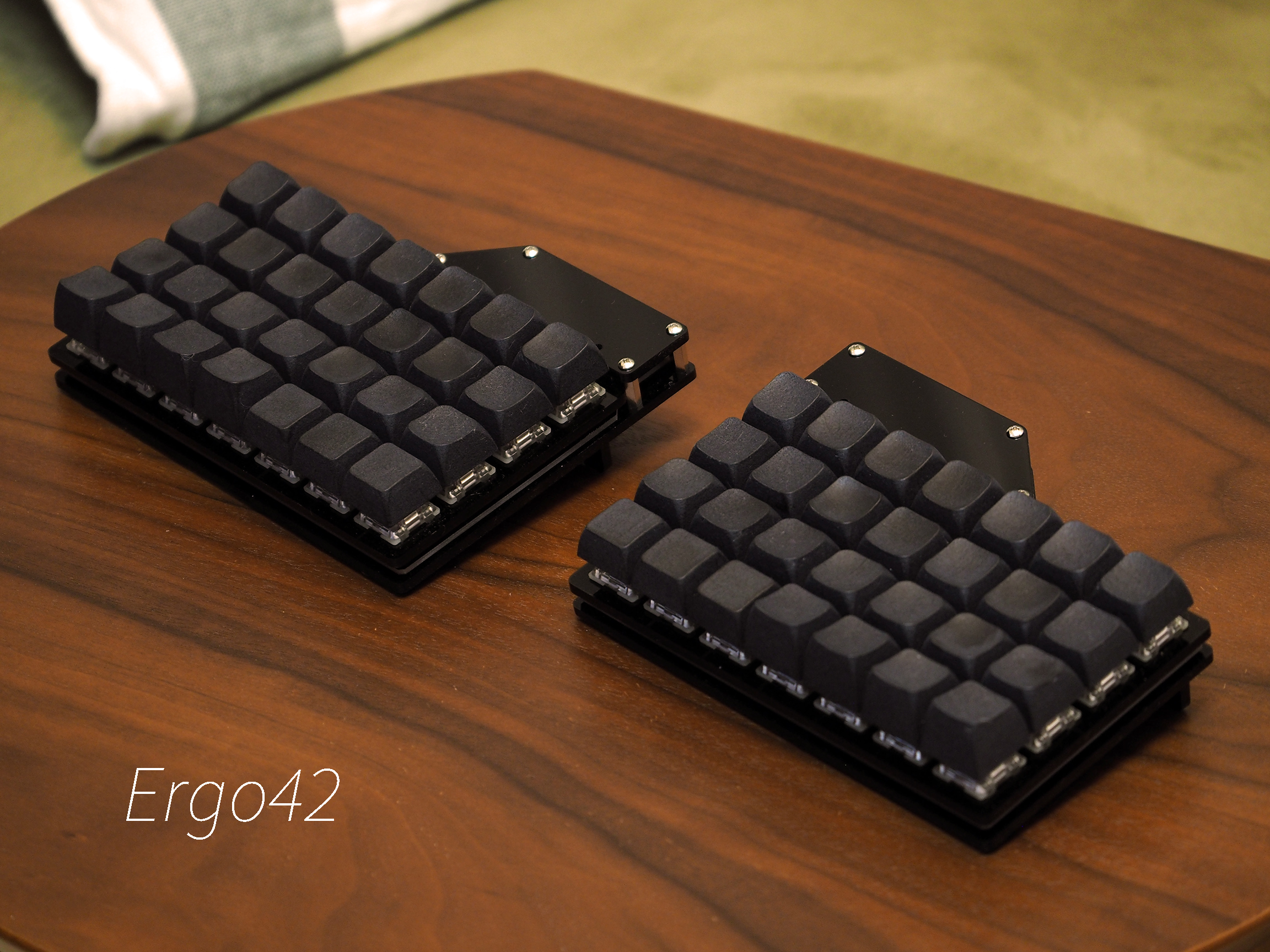
The Answer to the Ultimate Question of Life, the Universe, and at least Keyboards.
7x4 ortho linear split keyboard.
- 2 PCB
- 2 5V/16MHz Pro Micro compatible boards
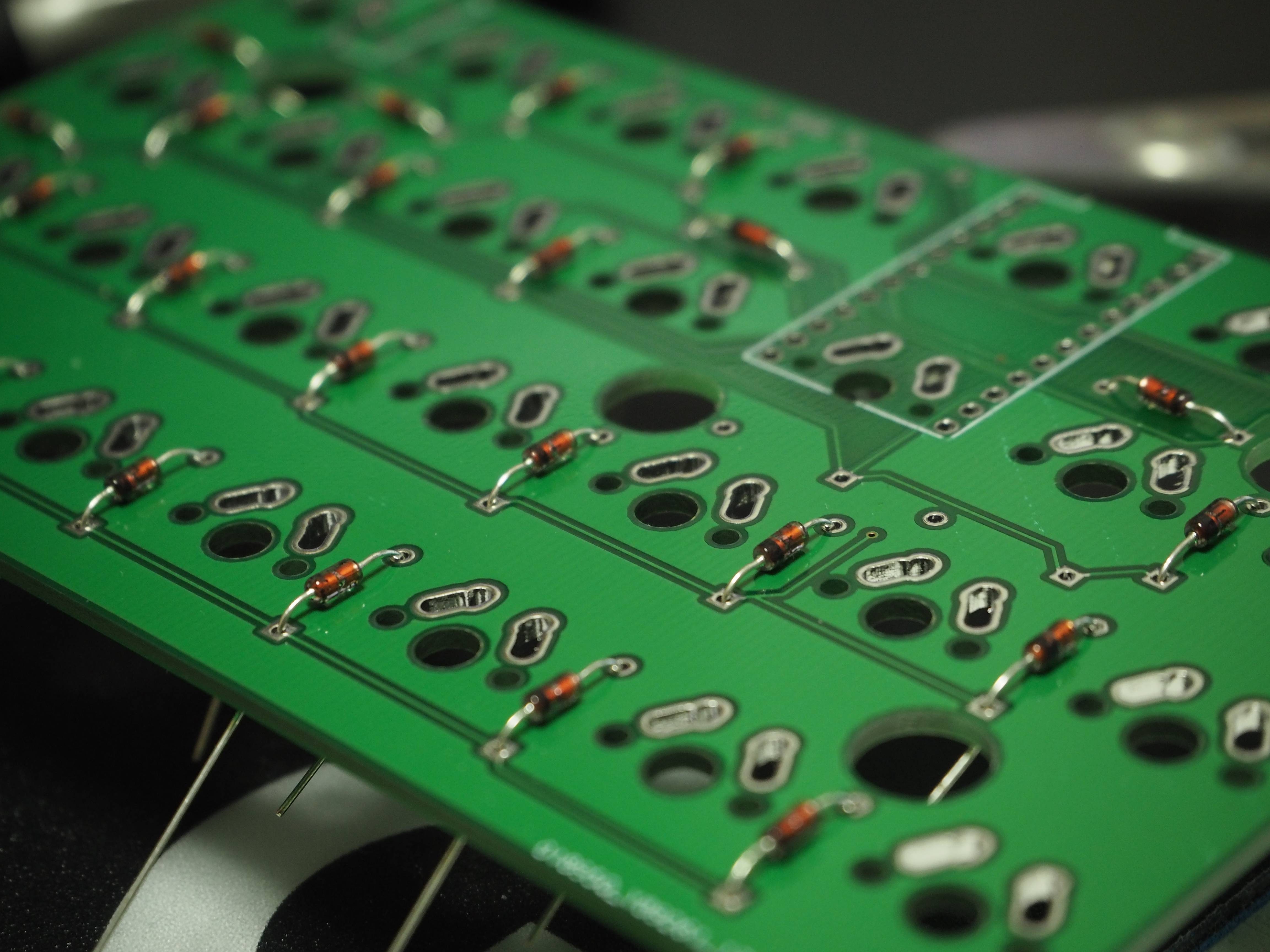
- 56 1N4148 diodes
- 2 MJ-4PP-9 TRRS jacks
- 2 Case plate set (available on this repo)
- 10 10mm M3 standoffs
- 20 6mm M3 screws
- 56 Switches of your choice
- 1 TRRS cable
The M3 screws may have a slight clearance issue with the keycap. Use a screw with a lower profile head.
Place the PCB as TRRS jacks on the inside, closest to one another.
- The left PCB will have the TRRS jack on the right
- The right PCB will have the TRRS jack on the left
Solder diodes on which side is depending on your switch plate's thickness. 3 mm thick acrylic plate may have diodes on any side. 5 mm one should have diodes on the other side of switches.
Tip: Only the side which opposites from switches is verified.
Double check your work. Black lines should be facing the square pad.
Mount the TRRS jack on the side opposite from your switches. It should be on the bottom.
Solder header pins for Pro Micro. DO NOT solder the Pro Micro at this time
Mount switches on the acrylic plate, set PCB to fit and solder switches. Nothing is difficult.
Ergo42's PCB is symmetrical but Pro Micro mount is different between left and right PCB.
- On the left PCB the Pro Micro's component side should be face to PCB
- On the right PCB the Pro Micro's component side should be back to PCB
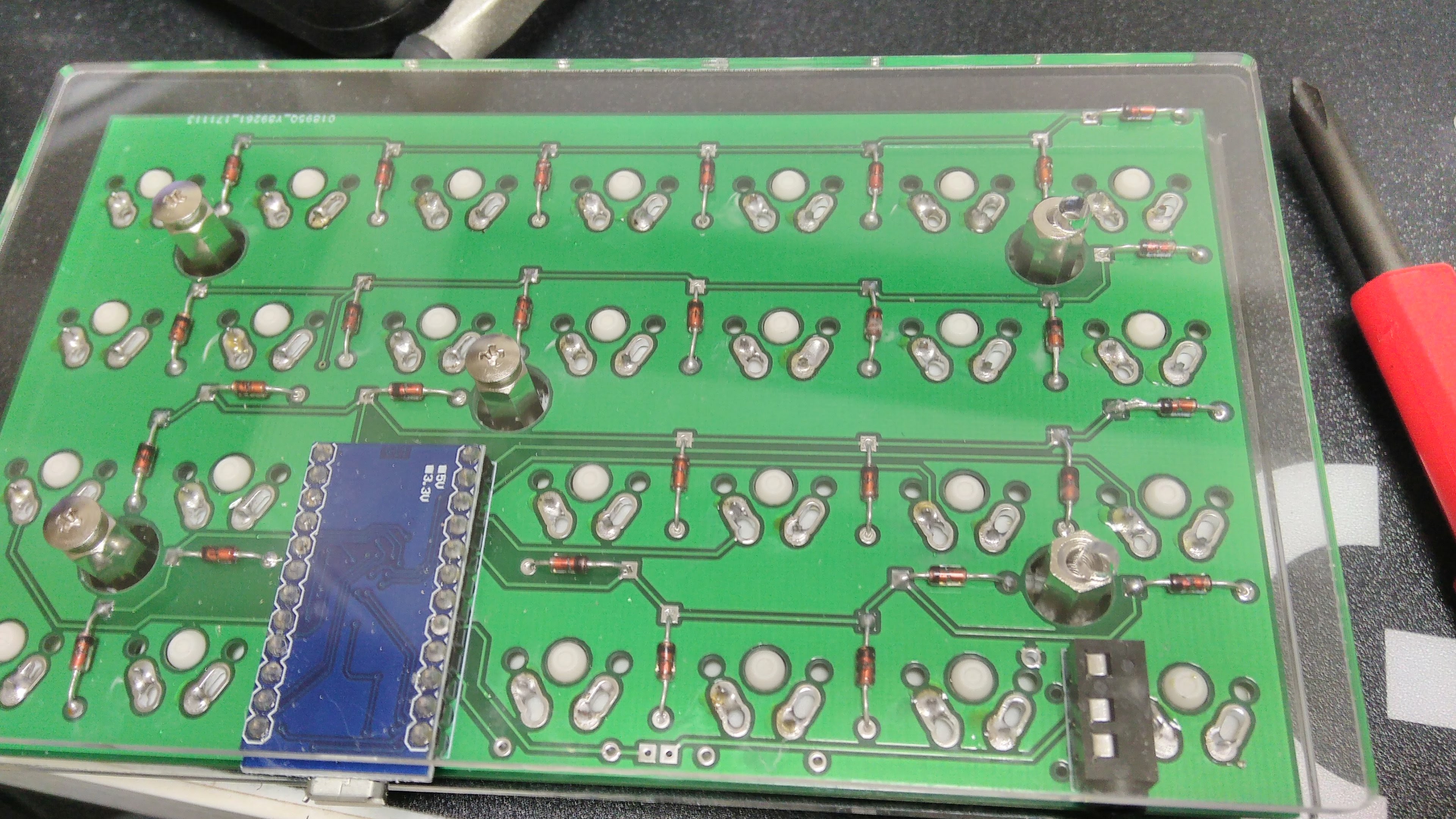
Pro Micro has no reset switch. You can solder tact switch between GND and RST pins here.
Tighten the screws with standoffs. Some vinyl pads may help the keyboard's stability. Install your keycaps.
QMK firmware for Ergo42 now abilable on this repo at ergo42 branch. This document doesn't cover how to build QMK. Prease refer to QMK documents.
Conntect the keyboard by usb cable to PC and run
$ make ergo42/rev1:default:avrdude
will build and try to flash your firmware. Follow the instractions that require to reset the Pro Micro.
This process may require privileges.