This project is based on the work of:
-
Holguer A Becerra (spanish), google translated version
HDMI (video) output using a DE0 Nano Development Kit.
-
Creating HDMI video using an FPGA.
-
HDMI output for NeoGeo.
-
HDMI 1.3a and 1.4 specification can be easily found on the internet, but CEA Standard CEA-861-D, to which is refered many times in the HDMI specification, was harder to find. IEC Standard 60958-3 (Digital Audio Interface: Part 3 Consumer Applications), which is needed to understand how digital audio is embedded into HDMI, I found only here.
Dreamcast 480p (VGA) output via HDMI with embedded 44.1kHz audio (no A/D conversion) directly from dreamcast's video/audio subsystems.
- 480i support
- Upscaling
- OSD
- EDID support
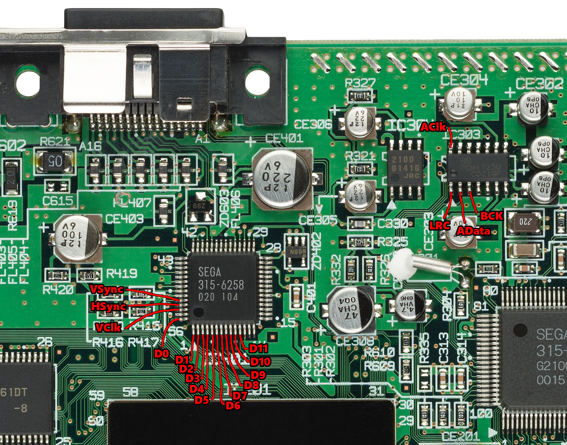
Luckily, the dreamcast uses an external video DAC (IC401), so we can tap into the signals here:
Video DAC on Schematic:

-
VSync (VSYNC) (pin 52)
-
HSync (HSYNC) (pin 53)
-
VClk (VCLK) (pin 54)
Video clock: double the pixel clock (54Mhz for 480p), because RGB values are transmitted in two clock cycles. (See below)
-
D0-D11 (pin 56, pins 1-11)
From Dreamcast Hardware Specification Outline (page 37):
From HOLLY, the 24bit RGB image information (each RGB 8bit) is sent in units of 12 bit to the Digital-Video-Encoder (video DAC/encoder). The original 24 bit image data is divided into 12bit(RGB [11:0]) of MSB (RGB [11:0] = R [7:0], G[7:4]) and 12 bit of LSB (RGB [11:0] = G [3:0], B [7:0]). Then it is sent to the 54 Hz clock (which is double the 27Hz VGA pixel-clock) in a synchronised manner where it alternates between MSB and LSB. For details refer to a separate specification design document.

For the audio part we can tap into the audio DAC (PCM1725) (IC303). The sampling rate is 44.1kHz.
Audio DAC on Schematic:

- LRC (DLRCK) (pin 1) Audio LR Clock (LVTTL)
- AData (DSD) (pin 2) Audio Data (LVTTL)
- BCK (DBCK) (pin 3) Audio Clock (LVTTL)
- AClk (DSCK) (pin 14) 256Fs audio clock signal (LVTTL)
Soldering points on Dreamcast mainboard:
Kynar wire soldered to video DAC:

It's quite tricky to solder kynar wire directly to the video DAC, because the round wire tends to slip between the legs of the chip, but with a relatively steady hand - mine is not :) - it should be manageable. Lots of flux is the key. Soldering to the audio DAC is be much easier, because of it's larger pitch :)
It should be possible to design a flatflex cable which is soldered directly to the VideoDAC - like the UltraHDMI is doing (UltraHDMI Flatflex)
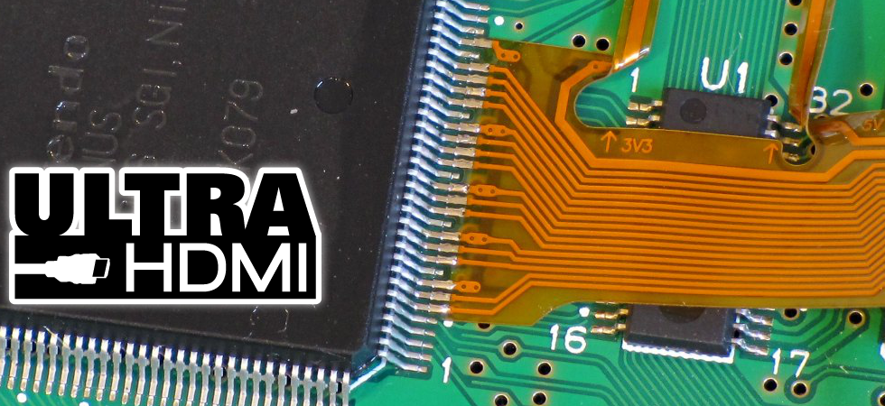
To enable "VGA" output, you either have to plugin any dreamcast VGA cable, or pull pins 6 and 7 of the dreamcast video connector to ground (this should be done with a switch, to keep 480i capability).
The dreamcast is generating 720x480p (not VGA) according to EIA-CEA-861-D "720x480p @59.94/60 Hz (Formats 2 & 3)" (chapter 4.5), not "640x480p @59.94/60 Hz (Format 1)" (chapter 4.2), but uses only 640 pixels of the possible 720.
When tapping into audio, I highly recommend to solder 4 kynar wires to ground and create twisted cables for the audio signals. Without that I experienced major interference from the video lines.
Currently I am creating the HDMI output directly via the FPGA's LVDS outputs and a simple LVDS to TMDS converter and a breadboard HDMI plug, which is far from optimal, but working ok for 480p.
According to Holguer A Becerra (top of site) it should even work without any level conversion "since most CML (similar to TMDS) receivers already have AC / DC coupling", but without I didn't had any luck on my AV receiver.
LVDS to TMDS Converter:

LVDS to TMDS Converter on breadboard:

For a real product a real HDMI transmitter should be used (e.g. ADV7513).
I'm using a DE0 Nano SOC, which is quite overpowered for this job (Cyclone V). It should be possible to use at least a Cyclone III or even a Cyclone II.
The project was recently updated to Altera Quartus Prime 16.1.2 (now Intel), which is available for free from their website. Just open FPGA/DCx.qpf project and you should be able to compile it.
Project Photo:
