Custom PCB with Esp 12F device (first version)

- Function of the switches
- How the buttons work
- How to calibrate buttons
- Parts list
- Schematic and EasyEDA project
- Programming Esp-12F
- Additional info
- Pictures

There are 2 switches at the top of the PCB. The one of the right is a power switch. The one on the left connects GPIO 0 of Esp-12F to GND (allowing it to be programmed). "W" - working mode, "P" - programming mode.
There are 6 buttons, Esp-12F has only 9 "general purpose input-output" (GPIO) pins (excluding RX and TX pins), 5 of them are used to connect RFID module, 2 of them are used to connect the display. As you can see there is not many pins left, for that reason all the buttons are connected to "analog to digital converter" (ADC) pin. The program reads voltage of the ADC pin and determines what button is pressed depending on the voltage. Resistors with different values are connected to buttons resulting in a set of voltage dividers.

When you buy resistors they usually have a percentage value (tolerance) in their description. That percentage (e.g. 5% or 1%) is how innacurate may be the resistors. For example:
1k resistor (1000 Ohm) with 5% tolerance can have the real resistance of 1.05k (1050 Ohm).
1k resistor (1000 Ohm) with 1% tolerance can have the real resistance of 1.01k (1010 Ohm).
As you can see the lower the tolerance the better the accuracy.
For this project I used 5% resistors, the inaccuracy of them as well as the changing voltage of the battery (as it discharges) influences the analog readings used to detect buttons being pressed. This is solved in the following 2 ways:
- The code auto adjusts the expected readings of all buttons (that is the reason for the 10k resistor that pulls ADC high even when no buttons are pressed, it provides the reading that decreases respectively to battery level and becomes reference point to adjust other expected readings).
- The readings of the ADC pin when buttons are pressed have to be copied into the code (Buttons.cpp file) which is described in the following section.
First get the reading values for each button when it's pressed, see this video on how to do it:
https://www.youtube.com/watch?v=T5_B_4qfb1Y
(values in the top-right corner are the readings to get)
In the video I navigate to "buttons calibration" from the menu and well working buttons are required for that so it is the best to enter that "button calibration" mode programatically by temporarily replacing 1 line from GUI.cpp in the void GUI::Init() method. The line to replace is:
gui_mode = MODE_INTRO; It should become:
gui_mode = MODE_BUTTON_CALIBRATION_VIEW;This way after uploading the code and turning on the device you'll see the numbers presented in the video that will finally have to be copied into the following part of Buttons.cpp file:
ButtonMap buttonMap[BUTTON_COUNT] = {
 44.5, BUTTON_NONE, "NONE", [](){},
 82.0, BUTTON_UP, "UP", [](){},
 150.0, BUTTON_DOWN, "DOWN", [](){},
 243.0, BUTTON_LEFT, "LEFT", [](){},
 342.0, BUTTON_RIGHT, "RIGHT", [](){},
 480.0, BUTTON_YES, "ACCEPT", [](){},
 660.0, BUTTON_NO, "DECLINE", [](){},
};- PCB (£5.57 from JLCPCB for 10 copies)
OSH Park is too costly (because of the size of the board), it's much cheaper to order from JLCPCB in this case. I listed few assembled PCBs on Tindie, if you need the plain PCB without any parts just let me know.
- Esp-12F (£2)
- Display (4-pin I2C SH1106) (£3)
- RFID module (RC522) (£1)
- Battery (Li-on 3.7V 350mAh 303040) (£4)
It just fits perfectly
- Voltage regulator AMS1117-3.3V (£1.5)
- Buttons (6x 6*6*5mm silicone silent SMD) (£2)
- Switches (2x MSK-12C02) (£2)
-
0603 SMD Resistors (~£0.6 each type, it may be cheaper to find a ready set of different values)
- 2x 10k
- 1x 4.7k
- 1x 2.2k
- 2x 1K
- 1x 680 Ohm
- 1x 470 Ohm
- 1x 220 Ohm
-
Standard through-hole resistors (£2)
- 1x 100k
- 1x 220k
These are required because PCB is not perfect and requires cutting one trace and soldering 2 of these. See Additional info section.
-
Capacitors (~£1 each type)
- 2x 10uF
- 1x 1uF
- Male 51005 2.0mm connector (£2)
Beware because they're selling female as male and vice-versa, I didn't pay attention to the pictures and had to order again after receiving female connector that supposed to be male. This connector is not essential for this device, it just allows charging it conveniently with a charger like this.
https://easyeda.com/michalmonday17/rfid-cloner-without-cp2102
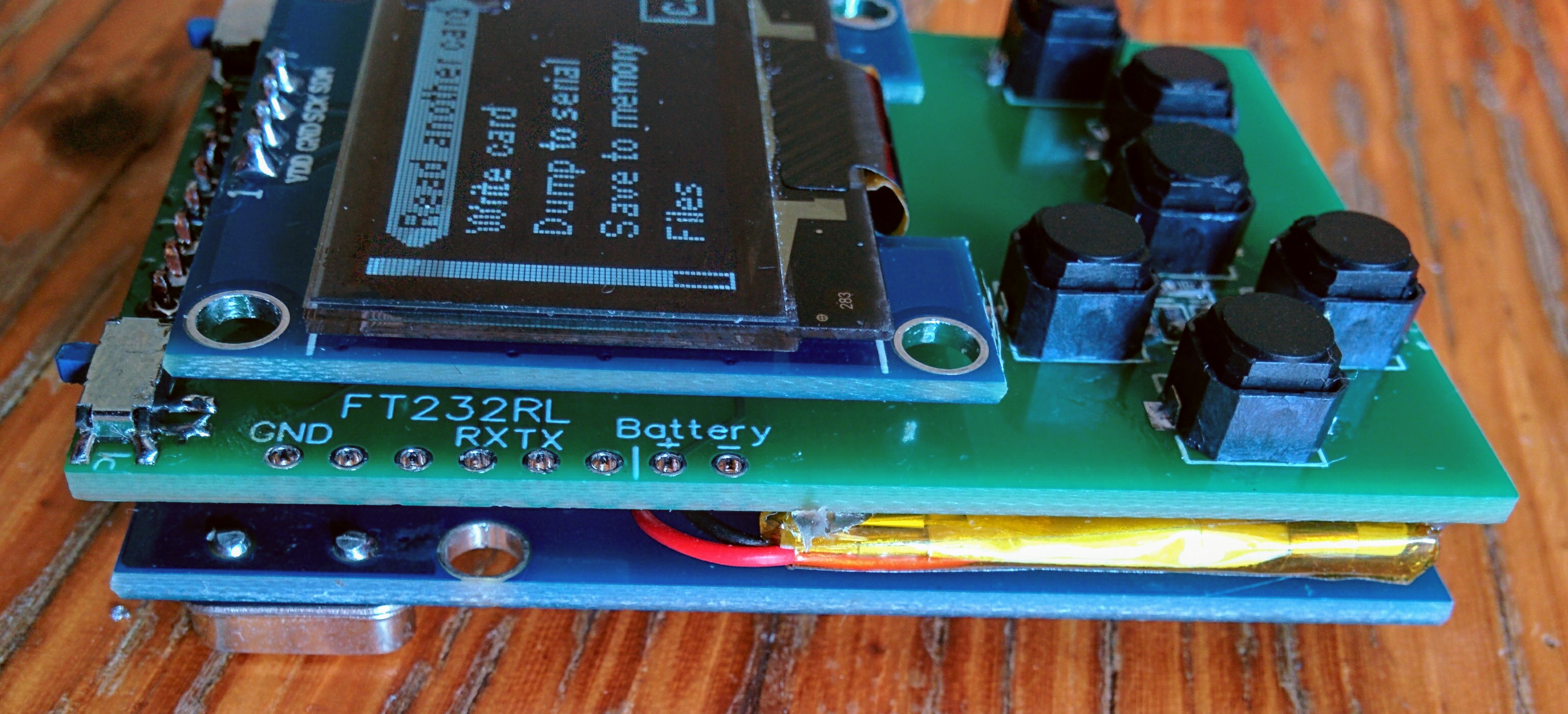
FT232RL module is required.

The PCB has pins at the side that fit that module perfectly, FT232 can be insterted and with a little pressure no soldering is required.


2. Insert the FT232RL module into the device as shown on the images above, then plug FT232RL into USB port in your PC.
Esp8266 for Arduino - the Installing with boards manager section (in README.md of the linked github repository) explains how to install it.
The three additional libraries (Rfid, Esp8266 OLED, LinkedList) should be put in the "libraries" folder on the Arduino IDE installation path. On my PC it's:
C:\Program Files (x86)\Arduino\libraries
If you're not sure whether the you copied them properly, the structure of the folders/files should be as on the following example:
Arduino\libraries\LinkedList\README.md
Arduino\libraries\rfid\README.rst
Arduino\libraries\esp8266-oled-ssd1306\README.md
You can download the updated versions of these libraries (hoping they will work), or you can use the ones included in this repository which I recommend.
Download the whole repository, unzip it and navigate to: RFID-cloner\rfidCloner 2\src\rfidCloner_2\, then open rfidCloner_2.ino file. and select the following settings:
6. Press upload button in Arduino IDE and apply some "sideways" pressure on the FT232RL to make sure its' pins are in contact with the metal holes of the device at all time during upload (see gif below).

The code should start compiling and uploading.
7. After upload is complete, remove the FT232RL, slide the left switch towards letter "W" (meaning "working mode") and reset device by using right switch (power switch).
The PCB is not perfect and requires:
- cutting one trace
- adding 2 "through hole" resitors
- adding 1 wire connection
See image below:

There's a layer of around 2-3mm hot glue between the battery and RC522 module. RC522 cannot sit directly on the battery because it interferes with RFID communication (cards were unable to read or readings were incomplete until I moved it away).

Before soldering display and rfid module use hot glue or blue tac to position them. Re-positioning may bevery difficult if all the pins are soldered already.
From the back:


Comparison with previous version size/shape:
